|
1.27mm Dual row, Surface mount Header (Male)
BB02-NE061-XAX-380000 - rev1.4
Choose 3D file format:
BB02-NE081-XAX-380000 - rev1.4
Choose 3D file format:
BB02-NE081-XAX-38A000 - rev1.4
Choose 3D file format:
BB02-NE101-XAX-38A000 - rev1.5
Choose 3D file format:
BB02-NE141-XAX-380000 - rev1.4
Choose 3D file format:
Have an existing competitor part number and wondering whether we can offer an alternative? Try our cross reference tool to see if we have the part for you! Cross Reference
GradConn’s massive range of signal and power board to board connectors for parallel PCB mating can be baffling.
Our board to board stacking calculator is a step-by-step system to find the perfect combination for your design at the lowest cost.
Simply enter the PCB stacking dimension required, toggle between imperial and metric, and then narrow your search via multiple choices. The search automatically selects 0.5mm (.020”) either side of your desired PCB stack height, this is adjusted for both upper & lower tolerance, allowing you to view alternative options where your design is flexible.
Search by:
Connector Pitch: From 1.00mm (.039”) pitch thru to 5.08mm (.200”)
Number of rows: Single, dual, triple or quad row connectors.
PCB mount type: Surface mount, thru hole or a mixture of the two (for example a SMT header with a Thru hole socket).
The search includes all headers and sockets, including elevated parts. Boxed and polarised products are also included. Get Started
Whatever your application, GradConn offer connectors for end to end PCB mating in through hole and surface mount, with options for single, dual and triple row in a variety of pitches. View Guide
Need something non-standard? Let us know what you need and our experienced engineers will evaluate it for you. Custom Capabilities
This page shows the basics of materials and plating for board to board pin headers. View All Board to Board Connectors

Base pins are produced from either brass or phosphor bronze.
Base pins are underplated with nickel and a finish plating added for improved conductivity, high temperature protection and resistance to corrosion and wear. Finish plating is available in variants of gold or tin.
See GradConn's whole range of board to board connectors here.
The images below shows examples of how customers might use GradConn's board to board elevated headers to connect PCB's in parallel stacking applications. Viell All Elevated Connectors
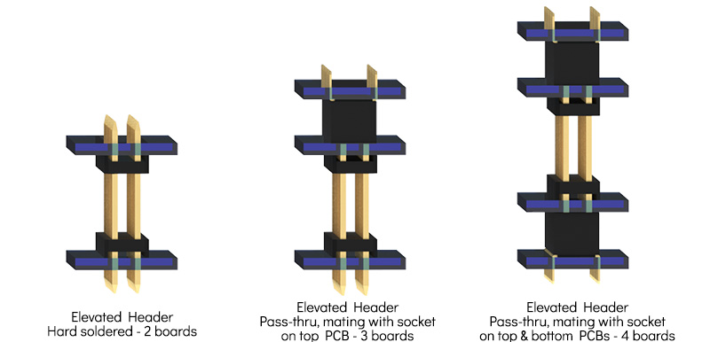
This is a basic building block of board to board connector design. From the left, the first image shows a thru hole stacking header hard soldered into two PCB's.
The next image shows a thru hole elevated header passing thru a mid PCB and going onto connect with a thru hole socket on the top PCB.
The final image shows an SMT socket on the bottom board, a stacking thru hole header and pass thru application, and a thru hole socket on the top PCB.
Resources:
GradConn's Parallel PCB stacking height calculator, this tool allows you to to define the PCB stack height you seek and filter by connector pitch, number of rows and termination types. You may search in metric or imperial and can even add upper and lower tolerances to see solutions which may be close to your ideal height.
GradConn's board to board connector parametric search, we've filtered this to show all the elevated headers. Continue to filter by connector pitch, mount type, rows, and choose peg and polarisation options to suit your design.
Click to browse all board to board resources.
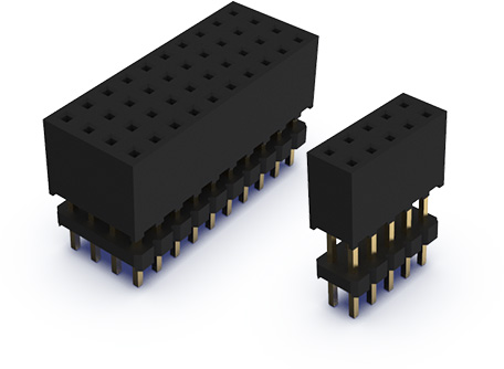
GradConn offer elevated PCB stacking sockets in 2.00mm and 2.54mm pitch, in single in line, dual in line, triple in line and quad in line configurations.
Customers often choose to use stacking sockets in applications where complete isolation of pins is required. Generally in parallel PCB stacking the conventional and most economical method is to use a standard socket and elevated header, however elevated header pins are generally exposed and therefore more at risk of shorting. Where shorting and safety is an issue customers may choose a standard pin header and plug to an elevated socket. When mated, header pins are totally enclosed within the body of the female housing.
Customers may also choose to use a thru hole stacking socket as a means of polarisation, for example, if two PCB stackers are required to physically or electrically then using one stacking header and one stacking socket allows operators to plug the PCB's together in the correct orientation.
View all Stacking Sockets
Learn all about the two different contact type we have in our socket types; Leaf spring and tuning fork
View female socket Board to Board Connectors

Sockets that accept mating header pins from the top or bottom are known as dual entry. More information can be found about these connectors here View Dual Entry Connectors
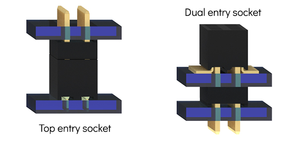
Using a dual or bottom entry socket allows applications that pass through a PCB. Holes are made in the PCB, the mating pin of the header passes through, enters the socket (receptacle) from below and males contact. An example of a dual entry socket is BB02-GQ, the drawing has two PCB layouts. The bottom entry layout includes holes for the pass through header pins.
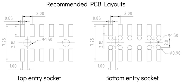
All receptacle drawings reference the socket contact point, which is the actual point of contact between the socket and the header pin. This allows you to approximate the header pin length, however there are more variables than a standard top entry application, including the thickness of PCB to be passed through. This is why GradConn do not recommend mating header pin lengths for bottom entry applications on product drawings. To define the recommended pin length accurately please contact GradConn with all the parameters, we'll then ask our engineering experts to define a header pin length. This will allow a contingency to cater for tolerances - and ensure whenever possible - that the pins don't emerge from the socket, which can cause shorting issues.
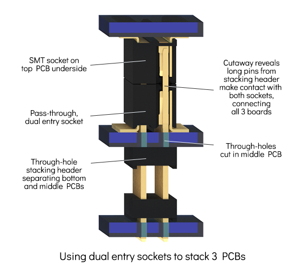
They can also be used to stacking, separating, and connecting multiple boards. The stacking header has a long pin capable of passing through the socket on the mid PCB and making contact with the socket on the top PCB.
If you need help with a board stacking applications please contact GradConn, our expert technical team are ready to help. Contact Us
A range of shrouded headers with keyed cut-outs and sockets with bumps offer polarisation which ensures connectors may be plugged together only in the correct orientation. View all Boxed Headers & Polarised Sockets
GradConn's board to board connectors include a wide range of boxed headers and polarised sockets. The combination of PCB headers with a outer 'boxed' insulator and mating socket connectors with the appropriate key allows you to design solutions which may be plugged together in the correct orientation only.
Elevated stacking polarised headers are available in all pitch options, allow polarised PCB stacking solutions. GradConn also offer dual row configurations with 1.27mm, 2.00mm & 2.54mm connector pitch spacing, including vertical and right angle headers and sockets, which allows both parallel and co-planar PCB mating.
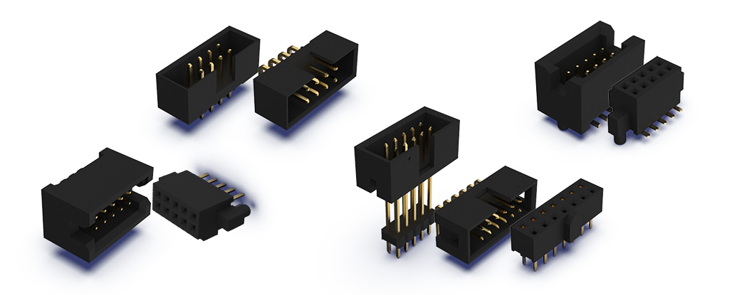
GradConns range of board to board connectors are available in single, dual row, triple and quad row in through hole and surface mount termination. Headers and sockets have a contact range of 2 – 120 and are available in vertical and horizontal orientation.
Tube or Tape and reel packaging (with or without film or caps) for pick and place assembly, is available on all SMT connectors.
All GradConn board to board connectors are RoHS compliant and suitable for high temperature processing, see drawings and product specification for more details.